
|
| |
|
Строительный блокнот Introduction to electronics 2.i Boost Convener Example Fig. 2.17 Variation of inductor current dc component / wiltl duty cycle, boost converter. 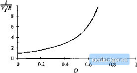 (2.36) Collecting terms, and equating the result to zero, leads the steady-state result -[d + D} + № = 0 (2.37) By noting that {D + D) = 1, and hy solving for the inductor current dc component 7, one obtains (2.38) So the inductor current dc component / is equal to the load current, V/R, divided by 1У. Substitutionof Eq. (2.34) to eliminate Vyields (2.39) This equation is plotted in Fig. 2.17. It can be seen that the inductor current becomes large as D approaches 1. This inductor current, which coincides with the dc input current in the boost converter, is greater than the load current. Physically, this must be the case: to the extent that the converter elements are ideal, the converter input and output powers are equal. Since the converter output voltage is greater than the input voltage, the input current must likewise be greater than the output current. In practice, the inductor current flows through the semiconductor forward voltage drops, the inductor winding resistance, and other sources of power loss. As the duty cycle approaches one, the inductor current becomes very large and these component nonidealities lead to large power losses. In consequence, the efficiency of the boost converter decTeases rapidly at high duty cycle. Next, let us sketch the inductor current (,(f) waveform and derive an expression for the inductor current ripple Aig. The inductor voltage waveform rj(t) has been already found (Fig. 2,15), so we can sketch the inductor current waveform directly. During the first subinterval, with the switch in position 1, the slope of the inductor current is given by dt - 1. ~ I (2,40) Likewise, when the switch is in position 2, the slope of the inductor current waveform is Kig, 2.18 Doosl coiivenei- iiiductnr current waveftirm Дг). 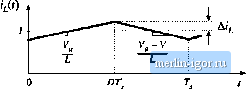 dt ~ L ~ L (2.41) The inductor current waveforrn is sltetclied in Fig. 2.IS. During the first .subinterval, tlie change in inductor current, 2A(j, is equal to the .slope multiplied by the length tif the subinterval, or tAl) Solution for Arleads to (2.43) This expression can be used to select the inductor value L such that a given value of Д(, is obtained. Likewise, the capacitor voltage vit] waveform can be .sketched, and an expression derived for the [)utput voltage ripple peak magnitude Av. The capacitor current waveform ijit) is given in Fig. 2.15. During the first subinterval, the slope of the capacitor voltage waveform vifj is dt ~ С НС (2.44) During the second subinterval, the slope is dt ~ С ~C RC (2.45) The capacitor voltage waveform is sketched in Fig, 2.19. During the first subinterval, the change jn capacitor voltage, -2Ai, is equal to the slope multiplied by the length of the subinterval: -2Av--DT Solution for Дт yields (2.46) Fig, 2.19 Boost converter output voltage waveform v{t). 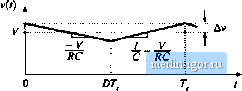 2.4 Сик CoimimExample (2.47) This expression can be used to select the capacitor value С to obtain a given output voltage ripple peak magnitude Av. 2.4 <tVK CONVERTER EXAMPLE As a second example, consider the converter of Fig. 2.20(a). This converter performs a dc conver-.sion function similar to the buck-boost converter: it can either increase or decrease the magnitude of the dc voltage, and it inverts the polarity. A practical realization using a transistor and diode is illustrated in Fig. 2.20(h). This converter operates via capacitive energy transfer. As illustrated in Fig. 2.21, capacitor is connected through to the input source while the switch is in position 2, and source energy is stored in C. When the switch is in position 1, this energy is released through i-j to the load. The inductor currents and capacitor voltages are defined, with polarities assigned somewhat arbitrarily, in Fig. 2.2()(a). In this section, the principles of inductor volt-second balance and capacitor charge balance are applied to find the dc components of the inductor currents and capacitor voltages. The voltage and current ripple magnitudes are also found. During the first subinterval, while the switch is in position 1, the converter circuit reduces to Fig. 2.21 (a). The inductor voltages and capacitor currents are: 4 = V. Vn = - Vj - Ъ (2.4s) 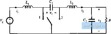 + V, - *lg. 2,20 Cuk converter: (а) with ideal switch, (b) practical realization using MO.SKET anJ Jiudc. |