
|
| |
|
Строительный блокнот Introduction to electronics 15 V Switch network h 2 15цН -I- ? 50 hF 20 n <b) Averaged switch model dit): d(t) d(t) L, gl5nH I 50 nF 20 a Fig. 7.S3 Buck-boost converter example: (a) converter circuit; (b) averaged circuit model of tlte converter. obtained from the switching circuit. Simulations of averaged circuit models can be u.sed to predict converter .steady-state aud dynamic responses, as well as converter losses and efficiency. 7.4.A Example: Averaged Switcli Modeling uf Switcliing Losses Switching los.ses can also be modeled via averaged switch modeling. As an example, consider again the CCM buck convetter of Fig. 7.48(a). Let us suppose that the tratisistor is ideal, and that the diode exhibits reverse recovery described in Section 4.3.2. The simplified switch waveforms are shown in Fig. 7.55. Initially, the diode conducts the inductor current and the transistor is in the off state. When the transistor turns oil, a negative current Hows through the diode so that the transistor current i, exceeds the inductor current. The time it takes to remove the charge stored within the diode is the reverse recovery time t. Waveform obtained by simubtion of the averaged model , Waveform obtained by simulaiion of the switching circuit model 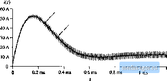 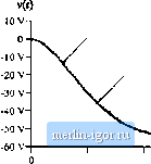 Waveform obtained by simulation of Ihe averaged model Waveform obtained by simulation of the switching circuit model 0.2 rm 0.4 ms O.G ms ( 0.8 ms t nts 1.2 ms 1.2 ms Fig. 7,S4 Waveforms obtained by simulatioji of the switching convertei circuit shown in big, 7.53(a) and by simulation uf the averaged circuit model of Fig. 7.53(b) Area  Fic> 7.55 Switch wavefonns, buck converter switching loss example, AC Equivakm Circui! Modeling
Fig. 7.S6 Large-signal averaged switcli model for the buck converter switching kiss example. It is assumed that the diode is snappy, so that the voltage drop across the diode remains small during the reverse recovery time, After the diode reverse recovery is completed, the diode turns off, and the voltage V.J across the diode qtiicklyjninps to the input voltage = v. For this simple example, conduction losses and Other switching losses are neglected. Let us select V(0 and /(O as the independent terminal variables of the two-port switch network, and derive expressions for the averaged dependent terminal waveforms ((\(0)r. and (vjO)), The average value of ((() is equal to the area under the lj(0 waveform, divided by the switching period (7.159) The quantity dij) is the effective transistor duty cycle, defined in Fig. 7.55 as the transistoron-time minus the reverse recovery time, divided by the switching period. The average value of VjCO is equal to: {v,(0)., = rf(v,(r)) (7.160) Equations (7.159) and (7.160) constitute the averaged terminal relations of the switch network. An equivalent circuit corresponding to these relationships is constructed in Fig. 7.5(i, The generators that depend on the effective transistor duty cycle d{t) are combined into an ideal transformer. To complete the model, the recovered charge and the reverse recovery time (, can be expressed as functions of the current {iit)) 120]. This is a large-signal averaged switch tnodel, which accounts for the switching loss of the idealized waveforms of Fig. 7.55. If desired, this model can be perturbed and linearized in the usual manner, to obtain a small-signal ac switch model. The model of Fig. 7.5Й has the following physical interpretation. The transistor operates with the effective duty cycle d{t). This is the turns ratio of the ideal dc transformer, which models the first-order switch property of lossless transfer of power from the switch input to the switch output port. The additional ctirrent generators model the switching loss. Note that both generators consume power. The total switching loss is: (7.161) These generators also correctly model how the sw itching loss increases the average switch input current. |