
|
| |
|
Строительный блокнот Introduction to electronics 6.2 Л Slwn Li-!! of Convener-! 145 5. Bridge 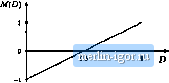 6- VfcJt/nJ-,/DAnjdn 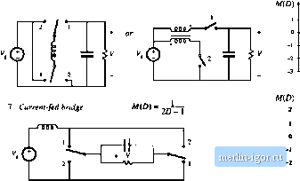 t d
S. Invent of Watleins-JtAmon M(D) 20-1 Wirv. I-; VQO -i Fig. 6.14 Continued lyzed. It has an inverting buclt-boost tliaracteristic, and exliibits nonpulsating input and output tenninal currents. The SEPIC (single-ended priinary inductance converter) [16], and its inverse, have noninverting buck-boost characteristics. The Cuk and SEPIC also exhibit the desirable feature that the MOSFET source terminal is connected to ground; this simplifies the coitstructioit of the gate drive circuitry. Two-inductor converters having conversion ratios M(D) that are biquadratic functioits ofthe duty cycle D are also numerous. An example is converter4 ofFig, 6.15 [17]. This converter cait be realized using a single transistor and three diodes. Its conversion ratio is M{D) =0. This coitverter inay find use in nonisolated applications that require a large step-down of the dc voltage, or in applications having wide variations in operating point. 1. tuk 6 / 1 d 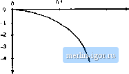 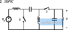 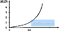 3. Inverse of SEPIC ЩО) = 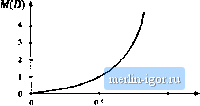 1 D 4. Bucfc плпг W(D) = тлпр M(CI) 1 Fig. 6.15 Several mernbers of ihc basic class of single-input single-uutput-eoavciters contaiiiing two Inductors. TRANSFORMER ISOLATION In a large nuinber of applications, it is desired to incorporate a transformer into a switching converter, to obtain dc isolation between the converter input and output. For example, in off-line applications (where the converter input is connected to the ac utility systein), isolation is usiially reciuired by regulatory ageu- hit) iV(f} 4(> Ideal uanstonmer Fig, 6Л6 Simplified moJel of a itiiiltiple-windini; transfomier: (a) schcmiilic symbol, (b) cquivalenl circoi: ton-l.iiiling a magiietizine inductance and ideal transformer. eies. Isolation could be obtained in these eases by simply connecting a 50 Hz or 60 Hz transformer at the converter ac input. However, since transformer size and weight vary inversely with frequency, significant improvements can be made by incorporating the transformer into the converter, so that the transforiner operates at the converter switching frequency of tens or hundreds of kilohertz. When a large step-tip or step-down conversion ratio is reqiiited, the use of a transformer can allow better converter optimization. By proper choice ofthe transformer turns ratio, the voltage or current stresses imposed on the transistors and diodes can be minitnized, leading to improved efficiency and lower cost. Multiple dc outputs can also be obtained in an inexpensive manner, by adding multiple secondary windings and converter secondary-side circuits. The secondary turns ratios are chosen to obtain the desired output voltages. Usually only one output voltage can be regulated via control of the converter duty cycle, so wider tolerances must be allowed for the auxiliary otitput voltages. Сго.м ngiilalioii is a measure of the variation in an auxiliary output voltage, given that the main output voltage is perfectly regulated [18-20]. A physical multiple-winding transformer having turns ratio n:!i.:nf..., is illustrated in Fig. 6.16(a). A simple equivalent circuit is illustrated in Fig. 6.16(b), which is sufficient fortinderstanding the operation of most transformer-isolated converters. The model assumes perfect coupling between windings and neglects losses; more accurate models are discussed in a later chapter. The ideal transformer obeys the relationships (6.1fi) 0 = Hjii(f) 4-Н;Ь(г) + thiii) + . In parallel with the ideal transformer is an inductance i, called the magnetizing inductance, referred to the transformer primary in the figtire. Physical transformers inustcontain a magnetizing inductance. Forexample, sitppose wediscon-nect all windings except for the primary winding. We are then left with a single winding on a inagnetic core-an inductor. Indeed, the equivalent circuit of Fig. 6.16(b) predicts this behavior, via the magnetizing inductance. |
||||||||||||||||||