
|
| |
|
Строительный блокнот Introduction to electronics v,<f) ув(0 0 -v, 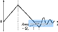 Fig. 4.54 Wuveforms of the cirtjuh of Tig-4.53, This charge is directly relateiJ to the energy storeiJ in the inductor during this interval. The energy W stored in the inductor is the integral of the power flowing into the inductor: VVl [i-T.CfWOA (4.16) During this interval, the applied inductor voltage is (4.17) Substitution of Eq. (4.17) into Eq. (4.1fi) leads to Чда = р (-V,V,(0.f (4.IS) Evaluation of the integral on the left side yields the stored inductor energy at Г = (j, or Ы(})12.\\\е right-side integral is evaluated by noting that is constant and by substitution of Eq. (4,15), yielding VQ. Hence, the energy stored in the inductor at t = is (4.19) or, the recovered charge multiplied by the source voltage. For; > ty the ringing of the resonant circuit formed by the inductor and capacitor causes this energy to be circulated back and forth between the inductor and capacitor. If parasitic loss elenients in the circuit cause the ringing amplitude to eventually decay to zero, then the energy becomes lost as heat in the parasitic elements. So diode stored minority charge can lead to loss in circuits that do not contain an active switching element. Also, ringing waveforms that decay before the end of the switching period indicate the presence of switching loss. 4J.4 Efficiency vs. Switching Freiuency Stippose next that we add up all of the energies lost due to switching, as discussed above: (4.20) This is the energy lost in the switching transitions of one switching period. To obtain the average switching power loss, we must multiply by the switching frequency: P Г (4.21) Other losses in the converter include the conduction losses modeled and solved as in Chapter 3, 4.4 Summary of Key Poiiia 100% П 90% Fig, 4,55 Efficiency vs. switcliing Irequcncy, based oit Eq. (4.22), using arbitrary choices for the values of loss and load power. Switching loss causes the efUcieticy tu decrease rapidly at high frequency. 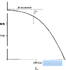 60% 10 kHz 1 MHz and other frequency-independent fixed losses Pjjj.j, such as the power required to operate the control circuit. The total loss is therefore Лил - Лии J PflifJ ttflftr which increases linearly with frequency. At the critical frequency (4.22) (4.23) the switching losses are equal to the other converter losses. Below this critical frequency, the total loss is dominated by the conduction and fixed loss, and hence the total loss and converter efficiency are not strong functions of switching frequency. Above the critical frequency, the switching loss dominates the total loss, and the converter efficiency decreases rapidly with increasing switching frequency. Typical dependence of the full-load converter efficiency on switching frequency is plotted in Fig. 4.55, for ;ui arbitrary choice of parameter values. The critical frequency/j,;, can be taken as a rough upper limit on the switching frequency of a practical converter. SUMMARY OF KEY POINTS How an SPST ideal switch can be realized using semiconduclor devices depends on the polarity of the voltage that (he devices must block in the off stale, and on the polarity of the current which the devices must conduct in the on stale. Single-quadrant SPST switches can be realized using a single transistor or a single diode, depending on the relative polarities of the off stale voltage and on stale current. 3. Two-quadrarif SPST switches can be realized using a tratisislor and diode, connecied in series (bidirectional-voltage) or in antiparallel (bidirectional-current). Several four-quadrant schemes are also listed here. 4. A synchronous rectifier is a MOSFET connected to conduct reverse current, with gate drive control as necessary. This device can be used where a diode would otherwise be required. If a MOSFET with sufficiently low/ijj is used, reduced conduction loss is obtained. 5. Majority carrier devices, including the MOSFET and Schottky diode, exhibit very fasi swilching times, controlled essentially by the charging of the device capacitances. However, the forward voltage drops of these devices increases quickly with increasing breakdown voltage. 6. Minority carrier devices, including ihe BJT, IGBT, and thyristor family, can exhibit high breakdown voltages with relatively low forward voltage drop. However, the switching times of these devices are longer, and are controlled by the limes needed lo insert or remove stored minority charge. 7. Energy is lost during switching transitions, owing to a variety of mechanisms. The resulting average power loss, or switching loss, is equal to this energy loss multiplied by the switching frequency. Switching loss imposes an upperlimit on the switching frequencies of practical converters. S. The diode and inductor present a clamped inductive load to the transistor. When a transistor drives such a load, it experiences high instantaneous power loss during the switching transitions. An example where this leads to significant switching loss is ihe IGBT and the curreni tail observed during its turn-off transition. 9. Other significant sources of switching loss include diode stored charge and energy stored in certain parasitic capacitances and inductances. Parasitic ringing also indicates the presence of switching loss. References [1] r. D. MlDDLEBROOK, S. CuK, and W. Behen, A New Battery Charger/Discharger Converter, IEEE Rower Electronics Specialists Confercnci:, 1978 Record, pp. 251-255, June 197S. [2J H. Mat.suo and F. kurokawa, New Solar Cell Power Supply System Using a Boost Type Bidirectional Dc-Dc Converter, IEEE Power Electronics Specialists Conference. 1982 Record, pp. 14-19, June 1982. [3j M. Ventueini, A New Sine-Wave-fn Sine-Wave-Out Conversion Technique Eliminates Reactive Elements, Proceedings Serctith Intenmticnial Solid-Stiitc Power Ctiiiver.sion Conference (Powercon 7), pp. E3.1-E3.13, 1980. [4j K. D. T. Nao, S. 6l;k, and R. D. Middlebrook, A New Flyback Dc-to-Three-Pha.4e Converter with Sinusoidal Outputs, IEEE Power Electronics Speciali.ifs Conference. 1983 Record, pp. 377-388. [5J S. ClIK, Basics of Switched-Mode Power Conversion; Topologies, Magnetics, and Control, Advances in Switched-Mnde Power Conversion, Vol. fl, Irvine CA: Teslaco, pp. 279-310, 1983. L6J L. GYLTOI and B. PELLY, Static Power Frequency Changers: Theory. Performance, and ApplicatioiKS. New York: Wiley-fnterscience, 1976. [7J r. S. Kagan and M, Chi, Improving Power Supply Efficiency with MOSFET Synchronous Rectifiers, Proceedings Ninth International Solid-Siaie Power Conversion Conference (PowerCon 9), pp. D4.1-D4.9, July 19S2. L8J R. BlanchaRD and P. E. Thieodeau, The Design of a High Efficiency, Low Voltage Power Supply Using MOSFET Synchronous Rectification and Current Mode Control, IEEE Power Electronics Special- |
|||||||||||||||||||||||||||