
|
| |
|
Строительный блокнот Introduction to electronics BJ Currmit Programmed Control S3S
Пв. B.23 Current pfograiniiied mode wavct ot4 s: (a) eortinuous conduction niiidcL (h) discoiitinuciiis conJucdon mode. when the transistor is on, the inductorcurrent increases with siope in given by: (B,24) It is assumed that voltage ripples are small so that the voltage v{t) across the inductor is approxiinately equal to the averaged value (Vj(O)j.. The length of the first stibinterval is (/)Г. The transistor is turned off when the inductor current reaches the peak value ij equal to: (B.25) In the second subinterval, when the transistor is off and the diode is on, the inductorcurrent decreases with a negative slope With the assumption the voltage ripples are small, the slope is given by: (B,26) The length of the second subinterval is d,{t)T, In CCM, the second subinterval lasts until the end ofthe switching cycle. Thcrcfofe: (E.27) In DCM, the current drops to zero before the end ofthe switching period. The length ofthe second sub-interval can be computed from: Output: duty cycle d
PARAMETERS: Inputs: {vo} КШг, Шг, Ы)}г, Fig. B.34 Current programmed mode (CPM) subcircuit. f>hT, (B.2S.) li the converter operates in DCM, t/j computed from Eq. (B.2S) is smaiier that I - d. If the converter operates in CCM, 1 - rf is smaller than d computed from Eq. (B,28). In general, the length of the second subinterval can be found as the smaiier of the two values computed using Eqs. (B.27) and (B.28). The average inductor current can be found hy computing the area under the inductor current waveform in Fig. B.23: mtdT.j ..i-- + d. m-,d,T, (B.29) The relationship given by Eq. (B.29) is valid ft)r both CCM and DCM provided that the second subinterval length is computed as the smaller of the values obtained from Eqs. (B,27) and (B.28). Based on Eqs. (B.24) to (B.29), an averaged CPM subcircuit model is constructed in the form shown in Fig. B.24. The inputs to the CPM subcircuit are the control input W,.U))r, - /-(ifCO)]-,. the measured inductor current RjiiJt)},., and the inductor voltages (f/f)) and (,v{t)).j. of the two subintervals. The tuitput of the subcircuit is the switch duty cycle d. The parameters tif the CPM subcircuit are the equivalent current-sense resistance Лу, the inductance L. the switching frequency /j = l/T , and the amplitude Vj, of the artificial ramp: (B.30) In the subcircuit implementation, the length of the second subinterval is computed as the smaller of the values given by Eqs. (B.27) and (B.28): rf 2 = MIN 1-d, (B.31) Next, the switch duty cycle is found by solving Eq. (B.29). There are many different ways the switch duty cycle can be expres.sed in terms of other quantities. Although niathematically equivalent to Eq. (B.29), these different ftmns of solving for d result in different convergence performance of the numerical solver in the simulator. In the CPM subcircuit available in the switcklib library, the duty cycle is found from: 12 V 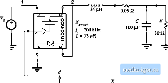
frf, 4ibf(3) W3) = 200 kHz L = 5SjJiH V, = 0.6 V Fig, B.2S CPM buck converter example. 2(,W + (/,}-2(i,.(f))-miJr, (B.32) which is obtained by inserting Eq. (B.25) into Eq. (B.29). This implicit expression (notice that d is on both sides of the equation) is tised by the numerical solver in the simulator to compute the .switch duty cycle rf. B.3.2 Example: Frequency RespotLses of a Buck Converter with Current Programmet] Contrtil To illustrate an application of the CPM subcircuit, let us consider the example btick converter circuit model of Fig. B.25. To construct this averaged circuit model, the switches are replaced by the CCM-DCMl averaged switch subcircuit. The control input to the CPM subcircuit is the independent voltage source f. Three dependent vtdtage sources are tised to generate other inputs to the CPM subcircuit. The controlled voltage source is proportitmal to the inductorcurrent l. The controlled voltage source £, is equal to v(l) - v(3), which is equal to the vohage {fi(0)r, applied across the indtictor during the first sub-interval when the transistor is on and the diode is off. The controlled voltage souice E2 is equal to v(3), which is equal to the voltage (iJj(t))j- applied across the indtictor during the second subinterval when the transistor is off and the diode is on. Ac simulations are performed at the quiescent operating point obtained for the dc value of the |
|||||||||||||||||||||||||||||||||||||||||||||||||||||||