
|
| |
|
Строительный блокнот Introduction to electronics (19,16) Ec]uatioii (19.16) is the desired re.sult. it .states that the dt conversion ratio of the resonant converter is approximately the same as the ac transfer function ofthe re.4onant tanli circuit, evaluated at the switching frequency/. This intuitive result can be applied to converters with many different types of tanlt circuits. However, it should be reentphasized that Eq. (19.16) is valid otily if the response of the tank circuit to the harmotiics of v(t) is negligible compared to the fundamental response, ati assutnption that is not always ju.stified. In addition, we have a.s.sumed that the switch network is controlled to produce a square wave and that the rectifier network drives a capacitive-type filter network. Finally, the transfer function H{s) is evaluated using the effective load resistance given by Eq. (19.9). 1*1.2 EXAMPLES 19.2.1 Series Resonant DC-DC Converter Example The .series resonant converter with switching frequency control is .shown in Fig. 19.4. Current-bidirectional two-quadiatit switches are necessary. Foi this circuit, the tank tietwork ctjnsi.sts of a series i-Ccir-cuit, and Fig. 19.14 can be redrawn as in Fig. 19.15. The tran.sfer function ti(s) is therefore: (19,17) where Transfer function H{s) 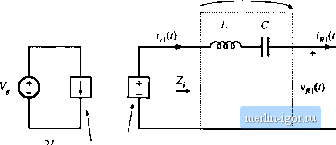 - sin (ш Fig. 19.15 Stciidy-state equivalent circuit of the series resonant converter. -cos(lp) 41 Series tanlinetworii sin (Ш)
The magnitude ofHiJtii,.), which coincides with the converter dc conversion ratio M = VVV is M=jmM)U- where (19,18) (19.19) The Bode diagrams of Z/j) and H{s) are constructed m Fig, 19.16, using the graphrcal construction inethod of Chapter s. The series resonant impedance Z{s) is dominated by the capacitor С at low frequency, and by the inductorL at high frequency. At the resonant frequency the impedances of the inductor and capacitor are equal in magnitude and opposite in phase; hence, they cancel. The series resonant impedance Zfs) is equal to atf-fy The transfer function \\ is consdructed graphically, by division of 2. by the II Z. II asymptotes of Fig. 19.16. At resonance, one obtains Я - KJK = 1. At frequencies above or below the resonant frequency, Z. \\ > and hence II W < I. So the conversion ratio M is less than or equal to 1. It can also be seen that a decrease in the load resistance R, which increases the effective quality factor Q, causes a more peaked response in the vicinity of resonance. Exact characteristics of the series resonant converter are pkttted in Fig. 19.45. Over what range of switching frequencies is Eq. (19.18) accurate? The response of the tank to the fundamental component of v/) raust be sufficiently greater than the response to the harmonics of v/l). This is certainly true for operation above resonance because Hs) contains a bandpass characteristic that decrea.ses with a single pole slope for/ >f[y For the same reason, Eq. (19.18) is valid when the switching frequency is below but near resonance. 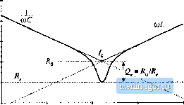 lig, 19.16 ConstruetioTi of the Bode diagrams of 7Д.Г) and Я(.?) for the scries resouant convertei-, However, for switching frequencies /, much less than the resonant frequency the sinusoidal approximation breaks down completely because the tank responds more strongly to the harraonics of Fig. 14,17 Excitation ot tlie tank network by the third hanntinic of the switching ftie-quency. S-witck ouiput voltage spectrum Resonant tank response Tank current spectrum v(/) than to its fundamental. For example, at / =/(,/3, the third harmonic of v,(f) is equal to/n and directly excites the tank resonance. Some other type of analysis tnust be used to understand what happens at these lower frequencies. Also, in the low-2 case, the approximation is less accurate because the filter response is less peaked, and hence does not favor the fundamental component as strongly. As shown in a later section, discontinuous conduction tnodes may then occur whose wavefortns are highly nonsinusoidal. 19.2.2 Subhiirinonic IModes of the Series Resonant Converter If the fi* harmonic ofthe switch output waveform v,(() is close to the resonatit tank frequency, n/, ~f, and if the tank effective quality factor is sufficiently large, then as illustrated in Fig. 19.17, the tank responds primarily to hartnonic л. All other coinponents of the tank wavefortns can then be neglected, and it is a good approximation to replace vj,t) withits n harmonic component: (19,20) This expression differs frotn Eq. (19.2) because the amplitude is reduced by a factor of i/n, and the fre- Fig. 19.18 The Hubharmonic modes of Ihc series resonant converter. These modes occur wheu the har-m[>nics of the switching fretjueney excite the tajik ics-onaiice. |
||||||||||||||||||||||||||