
|
| |
|
Строительный блокнот Introduction to electronics (rms turreiu) = \J !l + % \fj- me (16.19) = (rms voltage) By use ofEq. (1Й.Й), the average power is Vl f (16.20) : (mis voltage) Insertion of Eqs. (16.19) and (16.20) into Eq. (16.15) then shows that the power factor is unity. Thus, if the load is linear and purely resistive, then the power factor is unity rcg;irdlcss ofthe harmonic content of v(f). The harmonic content of the load current waveform i{t) is identical to that of v(/), and all harmonics result in the transfer of energy to the load. This raises the possibility that one could construct a power distribution system based on nonsinusoidal waveforms in which the energy is efficiently transferred to the load. 16.3.2 Nonlineui- Dynumical Load, Sinusoidal Voltage If the voltage vit) contains a fundamental component but no dc component or harmonics, so that - Vj = 13 = ... = 0, then harmonics in /(r) do not restdt in transmission of net energy to the load. The average power expression, Eq. (16.fi), becomes Л = -с>(ф,-0) C-iJ However, the harmonics in /(f) do affect the value of the rms current: Hence, as in example 1 (Fig. 16.2), harmonics cause the load to draw more rras ctirrent from the source, but not more average power Increasing the current harmonics does not cause more energy to be transferred to the load, but does cause additional losses in series resistive elements Rseries Also, the presence ofload dynamics and reactive elements, which causes the phase of the fundamental components of the voltage and current todiffer (8, - ф,), also reduces the power factor. The :os (Ф, - й) tetm in the average power Eq. (16.21) becomes less than unity. However, the tins value of the current, Eq. (16.22), dt)es not depend on the phase. So shifting the phase of /(;) with respect to vit) reduces the average power without changing the rras voltage or current, and hence the power factor is reduced. By substituting Eqs. (16.21) and (16.22) into (16.15). we can express the power factor for the sinusoidal voltage in the following form: (power factor) = cos (ф,-0,)) (16.23) = (distortion factor) (disptaeetneitt factor) So when the voitage contains no harmonics, then the power factor can be written as the prt)diict of two terms. The first, called the distortionfactor, is the ratio t)f the rms fundamental component of the current to the total runs value of the current (distortion factor) - (tuts fundamental current) (rms curreti:) (16,24) The second term of Eq. (16.23) is called the displacement factor, and is the cosine of the angle between the fundamental components of the voltage and current waveforms. The Total Harnwnic Distortion (THD) is defined as the ratio of the rms value of the waveform not including the fundamental, to the rms fundamental magnitude. When no dc is present, this can be written: (THD) = (16.25) The total hartnonic distortitm and the distortion factor are closely related. Comparison of Eqs. (16.24) and (16.25), with /ц = 0, eads to (distoition factor) = - V I + (THD) (16.26) This equation is plotted iit Fig. lfi.5. The distortion factor of a waveform with a moderate amount of distortion is quite close to unity. For example, if the waveform contains third harmonic whose magnitude is 100% Fig. 16.5 Distortion factor vs. total harmonic distortion. 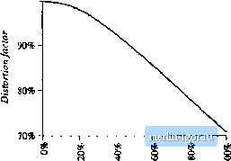 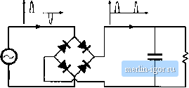 Fig, 16,6 Cotiventioiial peaJt detMtion rectifier,
100% THD = 136% Distortion factor = 59% 15% 15 I 3 5 7 9 11 13 15 17 19 Harmonic ntmber rig. 16,7 Typical ВС line current spectrum nf a peak detection rectifier. Harmonics 1 to 19 are shown, 10% of the fimdaraental, the distortion factor is 99.5%. Increasing the third harmonic to 20% decreases the distortion factor to 98%, and a 33% harmonic magnittide yields a distortion factor of 95%. So the power factor is not significantly degraded by the presence of harmonics unless the harmonics are quite large in magnitude. An example of a case in which the distortion factor is much less than unity is the conventional peak detection rectifier of Fig. 16.6. In this circuit, the ac line current consists of short-duration current pulses occurring at the peak of the voltage waveform. The fundamental component ofthe line current is essentially in phase with the voltage, and the displacement factor is close ft) unity. However, the low-order current harmonics are quite large, close in magnitude to that ofthe fundamental-a typical current spectrum is given in Fig. 16.7. The distortion factor of peak detection rectifiers is usually in the range 55% to 65%. The resulting power factor is similar in value. In North America, the standard 120 V power outlet is protected by ti 15 A circuit brealter. In consequence, the available load power quite limited. Derating the circuit breaker current by 20%, assuming typical efficiencies for the dc~dc converter and peak detection rectifier, and with a power factor of 55%, one obtains the following estimate for the maximum available dc load power: (ac voltage) (derated breaker current) (power factor) (rectifier efficiency) = (120V) (iiO%ofl5A) (0,55) (0,98) = 776W (16.27) The less-than-unity efficiency of a dc-dc converter would further reduce the available dc load power. U.sing a peak detectitm rectifier to supply a load power greater than this requires that the user install higher amperage anil/or higher voltage service, which is inconvenient and costly. The use of a rectifier |