
|
| |
|
Строительный блокнот Introduction to electronics 3.5 Example: liidiinioH of Seinkoiiducior Conducno)! Losses in the Boosi Conveiier Model 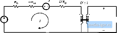 Fig, 3.28 Equivalent circuit model of (he boost cmweiter of Fig. 3,22, including ideal dc tran.sfcirmcr, inductor winding resistance, and MOSFET and diode conduction lusNes. Dividingby V gives the vuitage conversion ratio: DV о (3.34) It can be seen that the effect of the loss elements Rft К, уш1 Rp is to decrease the voltage conversion ratio below the ideal value (1Ш), The efficiency is given by Tl = P,JR ,. From Fig. 3.2S, P , = V/ and Z*, = УГУ!. Hence, 1 -- LTV /, R, + DR, , + DR L--a (Ъ.ЪЬ) For high efficiency, we require U-R vs. fi, + DR + DR (3.36) It may seem .strange that the equivalent circuit model of Fig. 3.28 contains effective resistances DH and whose values vary with duty cycle. The reason for this dependence is that the semiconductor on-resistances are connected in the circuit only when their respective semiconductor devices conduct. For example, at D = 0, the MOSFET never conducts, and the effective resistance DR, disappears from the model. These effective resistances correctly model the average power losses in the elements. For instance, the equivalent circuit predict.s that the power lo.ss in the MOSFET on-resistaiice is P-DR In the actual circuit, the MOSFET conduction loss is lR while the MOSFET conducts, and zero while the MOSFET is off Since the MOSFET conducts with duty cycle Д the average conduction loss is DIR , which coincides with the prediction of the model. In general, to predict the power loss in a resistor Й, we must calculate the root-mean-sqtiare current throtigh the resistor, rather than the average current. The average power loss is then given by { R- Nonetheless, the average model of Fig. 3.28 correctly predicts average power loss, provided that the inductor current ripple is small. For example, consider the MOSFET conduction loss in the buck converter. The acttial transistor ctirrent waveform is sketched in Fig. 3.29, for several values of inductor current ripple Д/, Case (a) corresponds to use of an infinite inductance L, leading tu zero inductor current ripple. As shown in Table 3.1, the MOSFET conduction loss is then given by LM., = DfR which Fig. 3,29 Tiatisistor curient waveform, tbi variuus filter inducLor values: (a) with a very large iiiductof, such Uiat Д( = 0; (b) with a typical Inductor valtje, auL-h that Ai= 0.1/; (й) witli a small ir)ductor value, chosen such that Ai-L 21 1.1 / agrees exactly wilh the prediction of the average model. Case (b) is a typical choice uf inductance L. leading to an inductor current ripple of Д; = 0.1Л The exact MOSFET conduction loss, cakidaied using the rms value of MOSFET current, i.s then only 0.33% greater than the prediction of the average model. In the extreme ca.se (c) where Дг = the actual conduction loss is 33% greater than that predicted by the a.verage model. Thus, the dc (average) model correctly predicts losses in the component nonidealities, even though rms current.s are ntjt calculated. The model is accurate provided that the inductor current ripple i.s small. Dtbk 3.1 Effect of inductor current ripple on МОЫ ГСТ conduction loss
3.ft SUMMARY OF KEY POINTS The dc transformer model represents ihe primary riintlions of any dc-dc converter: transformation otdc vohage and CLLn ent levels, ideally wilh 1009c efficiency, and contrtjl of the conversitin ratio M via the dtity cycle D. This model can be ettsily manipulated and solved using tamiliar techniques of convenlioDul circuit analysis. The model can be refined to account ftjr k)ss elements such as inductor winding resistance and semiconductor tm-resistances ;tnd forward vohage drops. The refined model predicts the voltages, currents, and efficiency of practical nonideal converters. In general, the dc eqtiivalent circtiil for aconverier can be derived from the inductor voh-second balance and capacitor charge balance eijualions. Eqaivalenl circuits are constructed whose loop and node equations coincide with the volt-second and charge balance equations. In converters having a pulsating input currenl, an additional equation is needed Lo model the convener input port; this equation may be obtained by averaging the converter input currenl. References [1] R. D. MlDDLEBROOK, A Continuous Model for the Tapped-Inductor Boost Convener, JEEE Power Electronics Specialists Conference, 1975 Record, pp. 63-79, June 1975. Problems [2] S. M. Cuk, MoJeling, Analysis, and Design ofSwilching Converters, Ph.D. (hesis, California Insiilute of Tethnology, November 1976. [3] G. Wester and R. D. MtOOLEBROOK, Low-Frequenoy CharaclerizatioD of Swilohed Dc-Dl- Conveners, IEEE Tranminotis on Aerospace and Elecuomc Systems, Vol. AES-9, pp. 376-385, May 1973. [4] R. D. Middles ROOK and S. M. Cltk, Modeling nnd Analysis Methods for Dc-lo-De Switching Conveners, IEEE liiteniaii/mal Seuiicoiiductor Power Converter Coiifereiice, 1977 Record, pp. 90-111. Problems In the buck-boosl converter of Fig. 3.30, the inJuctor has winJing resislanee fi. All other losses can be ignored. (a) Derive an expression for the nonideal vohage conversion ratio V/V. (b) Plot your result of part (a) over the range 0< Л < 1, for Н1Н=0, 0,01, and 0.05. (c) Derive an expression for the efficiency. Manipulate your expression into a form similar to Eq. (3.35) 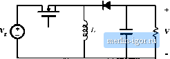 Fig. 3.30 Nonideal buck-boost converter. Problems 3,1 and 3.2. The inductor in the buck-boost converter ofFig. 3.30 has winding resistance R. All other losses can be ignored. Derive an equivalent circuit model for this convener. Your model should explicicly show the inpnt port of the convener, and shonld contain two dc transformers. In the converter of Fig. 3.31, the inductor has winding resistance Л. All other losses can be ignored. The switches operate synchronously; each is in position I forO</<DT, anJ in posilion 2 hn DT<t < T. Derive an expression for the noniJeal vohage conversion ratio VIV. Plot your result of pan [a) over ihe range 0<D< 1, for ft,/К = 0. 0,01, and 0.05. Derive an expression for the efficiency. Manipulate your expression into a form similar lo Eq. (3.35) 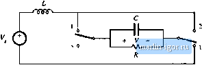 Fig. 3.31 Nonideal current-fed bridge converter, Problems 3.3 and 3.4. ЪА The inductor in the converter of Fig. 3.3! has winding resistance W, All other losses can be ignored. Derive an equivalent circuit moJel forlhis convener. |