
|
| |
|
Строительный блокнот Introduction to electronics Ijhzm (12.25) For large n, the perturbation magnituiJe tends to i 0 whetl I a I < 1 том I whericx[> 1 Therefore, for stability of the eitrrent programmed controller, we need to choose the slope of the artificial ramp m such that the characteristic value Cthas magnitude less than one. The artificial ramp gives us an additional degree of freedom, which we can use to stabilize the system for duty cycles greater than 0.5. Note that increasing the value of m causes the numerator of Eq. (12.25) to decrease, while the denominator increases. Therefore, the characteristic valueCt attains magnitude less than one for sufficiently large In the conventional voltage regulator application, the output voltage v(f) is well regulated by the converter control system, while the input voltage vJS) is unknown. Equadon (12.1) then predicts that the value of the slope is constant and known with a high degree of accuracy, for the buck and buck-boost converters. Therefore, let us use Eq. (12.6) to eliminate the slope tn from Eq. (12.25), and thereby express the characteristic value a as a function of the known slope njj and the steady-state duty cycle D: u = - (12.27) One common choice of artificial ramp slope is m{m, (12,28) It can be verified, by substitution ofEq. (12.28) into (12.27), that this choice leads to 0( = - 1 at D = 1, and to I a I < 1 for 0 < D < I. This is the minimum value of n! that leads to stability for all duty cycles. We will see in Section 12.3 that this choice of has the added benefit of causing the ideal line-to-output transfer function G,{s) of the buck converter to become zero. Another common choice of fn is = П2.29) This causes the characteristic value <f. to become zero for all D. As a result, iVj) is zero for any иЩ that does not saturate the controller. The system removes any error after one switching period 7 ,. This behavior is known as deadheat control, or finite settling time. It should be noted that the above stability analysis employs a quasi-static approximation, in which the slopes m, and ftij of the perturbed inductorcurrent waveforms are assumed to be identical to the steady-state case. In the most general case, the stability and transient response of a complete system employing current programmed control must be assessed using a system-wide discrete time or sampled-data analysis. Nonetheless, in practice the above arguments are found to be sufficient for selection of the artificial ramp slope m . Current-programmed controller circuits exhibit significant sensitivity to noise. The reason for this is illustrated in Fig. 12.11(a), in which the control signal ; (!) is perturbed by a small amount of noise Fig, 13,11 When noise pciturbs a controller signal such as i, a perturbation in tfie duty cycle results: (a) with no artificial ramp and small inductor curnsnt ripple, the perturbation i is lat:ge; (b) an artificial ramp reduces tlie controller gain, thereby reducing the peilurbation d. hit) Perturbed waveform Steady-state waveform Perturbed waveform 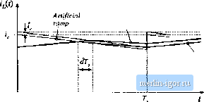 Steady-.state waveform DT, {D + )T, represented by l. Itcan be seeit that, when there is no artificial ramp and when the inductorcurrent ripple is small, then a small perturbation in leads to a large perturbation in the duty cycle: the coittroller has high gain. When noise is present in the controller circuit, then significant jitter in the duty cycle waveforms may be observed. A solution is to reduce the gain of the controller by introduction of an artificial ramp. As illustrated in Fig. 12.11(b), the same perturbation in i now leads to a reduced variation in the duty cycle. When the layout and grounding of the ctmtrollei circuit iittrodiice significant noise into the duty cycle waveftirm, it may be iiecessiiry to add ait artificial ramp whose amplitude is substantially greater than the inductor current ripple. A SIMPLE FIRST-ORDER MODEL Once the current programmed controller has been constructed, and stabilized using an artificial ramp, then it is desired to design a feedback loop for regulation of the output voltage. As usual, this voltage feedback iotip must be designed to meet specifications regarding line disturbance rejection, transient response, output impedance, etc. A block diagram of a typical system is illustrated in Fig. 12.12, containing an inner cunent programmed ctmtroller, with an tiuter voltage feedback loop. To design the outer voltage feedbaclc loop, nn ac equivalent circuit model ofthe switching converter operating in the current programmed mode is needed. In Chapter 7, averaging was employed to develop small-signal ac equivalent circuit models for converters operating with duty ratio control. These models predict the circuit behavior in terms of variations d in the duty cycle. If we could find the relationship between the control signal ijt) aitd the duty cycle dif) for the current programmed controller, then we could adapt the models of Chapter?, to apply to the current programmed mode as well. In general, the duty cycle depends not only on ifft), but also on the converter voltages and currents; hence, the current programmed controller incoфorates multiple effective feedbaclc loops as indicated in Fig. 12.12. Switching converter dit) Current programmed controller Converter voltages and currents tit) Compensator Fig. 12,11 Block diagram of a converter system incorpomting cuirent pn>grainmed control, In this section, the averaging approach is extended, as described above, to treat current pro-gramined conveilers. A simple first-order approximation is employed, in which it is assumed that the current programmed controller operates ideally, and hence causes the average inductor current {ii(.t)}j to be identical to the coutioi i,.(f). This approximation is jtistifred whenever the indtictor ctirrent ripple and artificial ramp have negligible magnitudes. The inductorcurrent then is no longer an independent state of the system, and no longer contributes a pole to the converter small-signal transfer functions. This first-order model is derived in Section 12.2.1, using a simple algebraic approach. In Section 12.2.2, a simple physical interpretation is obtained via the averaged switch modeling technique. A more accurate, but more complicated, model is described in Section 12.3. 122.1 Simple Model via Algebraic Approach: Buck-Boost Example The power stage of a simple buck-boost conveiter operating in the continuous conduction mode is illustrated in Fig. 12.13(a), and its inductorcurrent waveform is given in Fig. 12.13(b). The small-signal averaged equations for this converter, under duty cycle control, were derived in Section 7.2. The result, Eq. (7.43), is reproduced below: i/j)i};,+ijii) (12,30) The Laplace transforms of these equations, with initial conditions set to zero, are |