
|
| |
|
Строительный блокнот Introduction to electronics Fig. 10.23 Performance attained via optimal design procedure, parallel fiyij, circuit of 10,20(b). Optimum peak ftlter output impedance IIZ II and increase of filter hih-fre-quency gain, vs. ii - LJL. 30 dB 20 dB 10 dB - 10 dB 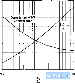 I Z II for a given choice of L) is described by the following equations: n 3-t-4n 1 + 2/1 Я / \/ 2(l + 4 where (10.34) The peak filler ouiput impedimce occurs al frequency U-lff 2,1- and has the value z , , = Vv4 The attenuation ofthe filter high-frequency asymptote is degraded by the facior (10,35) (10.36) (10.37) = 1+ (10.38) So, given an undamped LfC filler having comer frequency fp, and characteristic impedance Лду, and given a requirement for the maximum allowable output impedance Z, Цщ, one can solve Eq. (10.37) for the required value of n. One can then determine the reqiftred numerical values oft;, and Rf 10.4J fiy -f-t Series Damping Figure 10.2()(c;) illustrates tlie plaoemenl of damping resistor in series with inductor £y. Inductor L(, provides ade bypass to avoid significant power dissipation in Rj- To allow Rfia damp the filter, inductor should have an impedance magnitude that is sufficiently greater than Rj at the filter resonant frequency. Although this circuit is theoretically equivalent to the parallel damping RL case of Section 10.4.2, several differences are observed in practical designs. Both inductors must carry the full dc current, and hence both have significant size. The filter high-frequency attenuation is not affected by the choice of Л and the high-frequency asymptote is identical to that of the original undamped filter. The tradeoff in design of this filter does not involve high-frequency attenuation; rather, the issue is damping vs. bypass inductor size. Design equations similar to those of the previous sections can be derived for this case. The optimum peak filter output impedance occurs at frequency l.ffJ,ff 00.39, and has the value + [10.40) I * II flrnr ~ 0/ The value of damping resistance that ieads to optimum damping is described by 2(1 +n)[4 + [1 + п][а + Ц (10.41) For this case, the peak output impedance canuot be reduced bekivv Й/f(j via damping. Nonetheless, it is possible to further reduce the filter output impedance by redesign of iand C to reduce the value of R, 10.4.4 Cascading Filter Sections A cascade connection of multiple L-C fiher sections can achieve a given high-frequency attenuation with less volume and weight than a single-section L-C filter. The increased cutoff frequency of the multiple-section filter allows use of smaller inductance and capacitance values. Damping of each L-C .section is usually required, which implies that damping of each section should be optimized, Unfortuuately, the results of the previous sections are restricted to single-section filters. Interactions between cascaded L-C sections can lead to additional resonances and increa.sed filter output impedance. It is nonetheless possible to design cascaded filter sections such that interaction between L-C sections is negligible, In the approach described below, tlte filter output impedance is approximately equal to the output impedance of the last section, and resonances caused by interactions between stages are avoided. Although the resulting filter may not be optimal in any sense, insight can be gained that alloWS intelligent design of multiple-section filters with economical damping of each section. Additional filter section Existitig filter Fig. lft.24 Addition of a fdtet seetion at the input of an existing fdter. Consider tlie addition of a fiiter section to tiie inptit of an existing filter, as in Fig. 10.24. Let us assume that the existing filter has been correctly designed to meet the output impedance design criteria of Eq, (10.13): under theconditions Z/s) = 0 and v{s) = 0, ]\2 ]] is sufficiently small. It is desired to add a damped fiiter section that does not significantly increase [ Z, ([ Middiebrooks extra element theorem of Appendix С can again be invoked, to express how addition of the filter section modifies ZJjs): modified Z (s) = [z (i) Z (S) (10.42) where z,(,0=z (i) (10.43) is the impedance al the input port ofthe existing tiller, with its outpul port short-circuited. Note that, in this particular case, nulling v fs) is the same as shorting the filter ouiput port because the short-circuit current Hows through the if , source. The quantity Zr,j(0 = Z,(A). (10,44) is the impedance at the input port of the existing filler, with its ouiput port open-circuited. Hence, the additional filter section does not significantly alter provided lhat (10,45) Bode plots of the quantities Z and Zj can be constructed either analytically or by computer simulation, to obtain limits of Z, When II Z satisfies Eq. (10.45), then the correction factor (1 +ZJZy{\ ZJZji) is approximately equal to 1, and the modified Z is approximately equal to the original Z. To satisfy the design criteria (10.45), it is advantageous to select the resonant frequencies of Z to differ from the resonant frequencies of Zj,. In other words, we should stagger-tune the filter sections. This minimizes the interactions between filter sections, and can allow use of smaller reacrive element values. |